Cellular Rotary Phone
Contents
Project Scope
Description:
This is a deeper look into the Port-O-Rotary phone. We stuck the GM862 cellular module into an old rotary phone enclosure, and viola, it was an instant, ridiculous, hit.
Here we are going to breakdown the schematics and systems of the rotary phone.
Power
Really simple - the GM862 requires 3.8V and a Lithium Polymer outputs 3.7-4V. No regulator needed, but we will need a charger. We currently use an external charger from a third party company. Aubrey noted the GM862 has a built in Lithium-Ion charger that may work, we haven't tested it yet. Ideally we would stick a barrel jack in the back of the enclosure where the RJ11 telephone jack used to reside. Anyone have any recommendations?
Rotary Decoding
We use a PIC 16LF88 (remember we are at 3.7V! We need a low-voltage PIC!) to read the hook and rotary. Pretty simple switch decoding routine. We just read the opening/closing of the paddles behind the rotary. There are two - one set of paddles opens and closes for each number that passes by, the other set of paddles is normally open when the rotary is in the home position and closed while the rotary dial is moving. Reading this second set of paddles will tell us when the dialing of a single number is complete.
Finally, because we don't know how long of a number the user is dialing, the PIC waits for a 4 second timeout before sending the given phone number to the GM862. This way the user can dial any type number of any length : 911, 3035551234, and 011212465748.
Bell Ringer
The ringer circuit must use the 3.7VDC nominal from the battery and output ~80VAC to get the coil to kick the hammer between the two gongs. Tricky to say the least. Pete Dokter (mad genious) used a basic DC-to-DC step up IC to get the DC voltage up to a weak 60V. This 60V was then alternated through an H-Bridge to get ~110VAC. It works! But the DC-DC boost circuit can't sustain the high voltage for more than a few seconds - just about perfect because we just need to ring the bells for a second or two and then pause between rings.
The ringer circuit is a bit power hungry in stand-by (using ~150mA in standby!), so we use a p-channel MOSFET to power cycle the ringer sub-board. When the phone ain't ringing, the ringer board gets no power.
Schematics
Here's the good stuff. Well, it will be here once I can get to the updated schematics.
Audio Considerations
We hooked the handset mic and ear-piece directly to the GM862 without any external components. The mic was biased through a 10k resistor using the 3.7V off the battery. One would think that this would be a clean source of DC power, coming directly off a high current battery. In practice however, there is some horrendous buzzing in the ear piece. Funny thing, when we disconnect the mic, all the buzzing went away.
As usual, we should have read the f*ing datasheet.
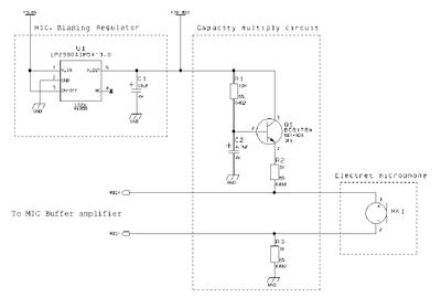
Hardware manual, page 27:
Here you can see a mildly complex electret mic biasing circuit. What is this? Well, an electret mic needs just a little bit of current to operate. Normally you can power the mic by just attaching one side to a 10k pull-up resistor. This circuit takes the 3.8V main power, and outputs a super clean 3V to biasing the mic. Perhaps getting rid of all the RF noise that the GM862 is putting onto the main power? No way! REALLY!? It works great. Why didn't we think of this before!? We use a basic 3.3V regulator and a couple caps and it works just as well. You can power the mic using the main 3.8V power, but expect some buzzing. To get rid of the buzzing, send that main voltage through a simple 3V or 3.3V regulator circuit and you'll be very happy.
Board Layout
The PIC is connected to GM862 in various ways. Obviously we need TX and RX to send commands and receive OK responses. The PIC also monitors the RI (Ring indicator) line, as well as controlling the On/Off line to turn on the GM862 (requires a 1-2 second pulse) when the board is powered up. The PIC controls the p-channel MOSFET to power the external ringer board and toggles the ring pins to get the bells to activate when the RI pin is fired (I forget if it's active high or active low...).
Things to Improve
Many of our phone customers have asked for an external power switch - currently you have to open the case to get to the power switch or to charge the battery. I always use my normal phone SIM card. Since I've got to pop the top to get the SIM card in, turning the unit on while I'm in there is no big deal. Someday, oh someday, we could put a SIM card slot on the side of the phone along with a charge jack and a power switch. Ohhh. Ahhh.
Documents
Schematics coming in a minute.
Footprints:
SFE Footprint Library
FP Name: All sorts of FPs used. GM862, SSOP-20 for the SMD PIC, SOT-23 for the MOSFET, Polarized connectors, etc.
Supplier Info:
Related Items:
GM862 Cellular Module


