MPPT Solar and Wind Power Boost Charge Controller
ALL MY PROJECTS ARE HERE: http://www.opencircuits.com/User:Definitionofis
This circuit is an analogue computer when run without a microprocessor. As revolutions per minute voltage rises, current is allowed to rise proportionally. The variable loading math is P = I(V-offset) and (V-offset)/I = R. It behaves like a fixed resistor load, R, although it is feeding a battery which has a hugely variable resistance) and I x R = V. The op amp pegs I equal to V. Read about source to load "impedance matching" elsewhere to understand the point of this.
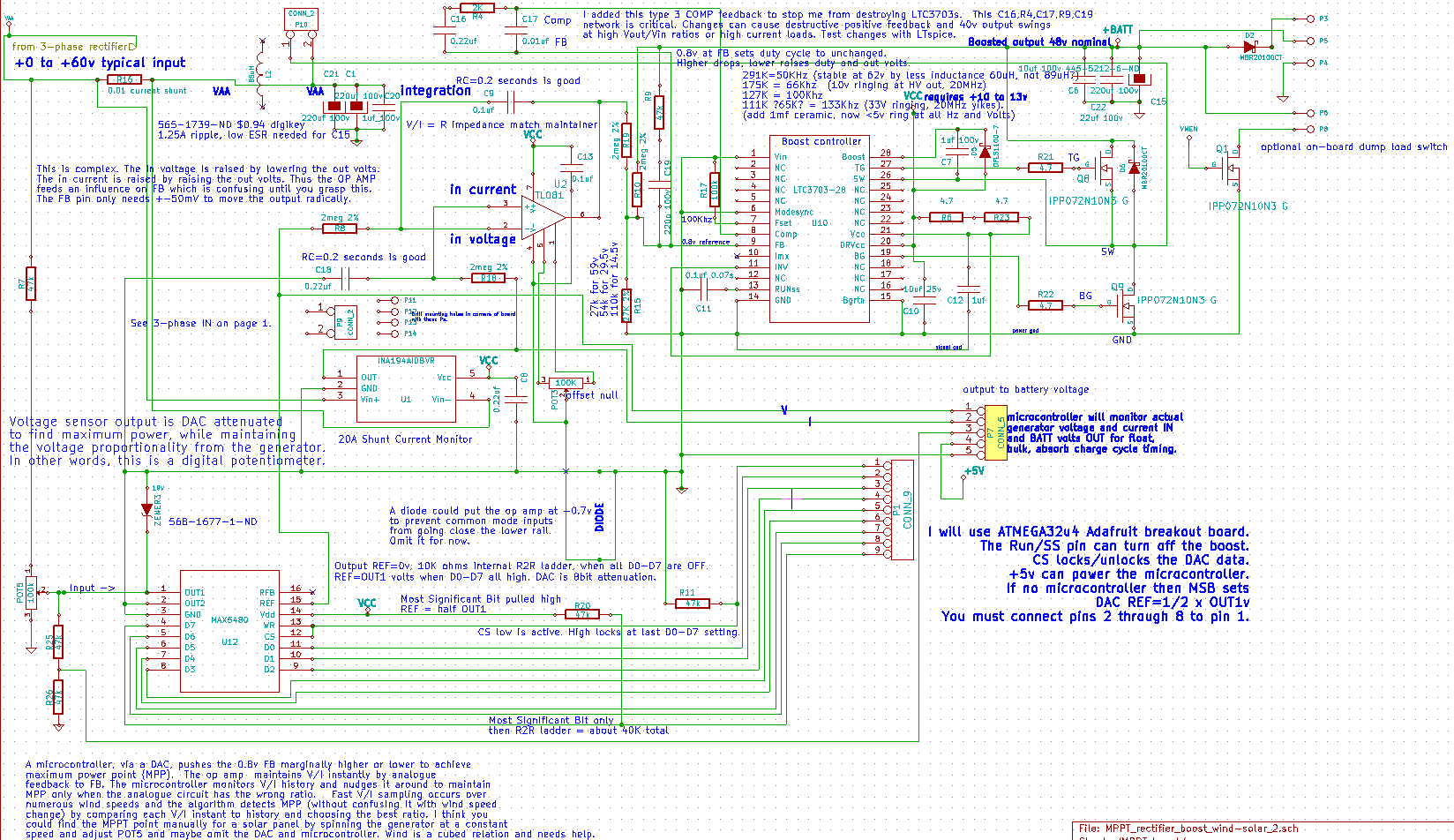
Here is a statement on the circuit diagram that explains the concept that the I and V input values are doing something to the output voltage to accomplish the above described load relationship. You understand that you can put more or less load on a generator. Here is how: [The IN voltage is raised by lowering the OUT volts. The IN current is raised by raising the OUT volts. Thus the OP AMP feeds an influence on FB which is confusing until you grasp this. The FB pin only needs +-50mV to move the output radically.] The input current and input volts you notice go in opposite directions. So you can move them around until they are equal, thus doubling current and doubling voltage is four times the power; 2 squared=4x power, 3 squared = 9x power, 4 squared = 16x power. If I and V are not made equal then power is indeterminate, unknown, not a squared relation, and the resistance V/I is changing and not maintaining impedance matching to the source of power.
How do you set the offset? A variable resistor in the circuit does that and you must select a value which is a manually selected setting of the maximum power point. Thought experiment: You could put a high wattage fixed resistor as the load and move that resistance up and down to find the maximum power transfer point and then remove that resistor load and attach this circuit in its place and move the offset variable resistor to cause that same favourable voltage across the input terminals and then you know this circuit is acting like the same fixed resistor. If you attached directly to the battery without this circuit, you do not get a fixed resistor effect.
Squared is suitable for solar. Apparently, wind is a cubed relation of wind speed to power energy from that wind, not squared, like this analogue calculation yields; eg. 2I x 2V = 4xPower. So, maybe you need the microprocessor for optimizing wind MPPT, but without a microprocessor will be interesting by experiment, not theory.
Anyway, my very high voltage battery needs a voltage boost because my wind generator rarely gets above battery threshold volts, which is 48v to 59v, depending on how full. It is doing integration calculus math via the op amp without a microprocessor. I added a pin header for optional microprocessor control, which I have not tested.
(Edit: Apr 2016: I have not looked at this for three years, and I am impressed with the elegance of my idea. It is handling hugely variable input voltage and unrelated variable output voltage, with an analogue circuit, like was typical of a circuit 40 years ago, before microprocessors became inexpensive.)
In summary, this circuit matches a low voltage solar or wind turbine input to a higher voltage battery. An analogue circuit will measure incoming current and voltage inputs to set the maximum power point tracking (MPPT) and boost the output voltage up to charge a higher, or equal voltage, battery. Input voltage range: 9v through 60v. Output battery voltages: 9v through 60v. MPPT will work only if the battery is higher than the input source. Otherwise, the circuit will act like a direct connection, source to output. It is based on the LTC3703 boost converter IC.
First successful power up testing of the board: https://vimeo.com/46944117 http://vimeo.com/tag:ltc3703
I will release the board layout diagram, which is critical to success. I burned up a lot of parts with spikes, before succeeding. I have to get the new KiCAD to read my old KiCAD files.
It is 9v through 60v MPPT boost to a 48v nominal lead-acid battery. It needs more testing after I attach a wind turbine. Otherwise, it seems to work, so far. How much power can it handle? I am not sure yet. I think 200 watts minimum and more with copper wire, instead of just the board traces.
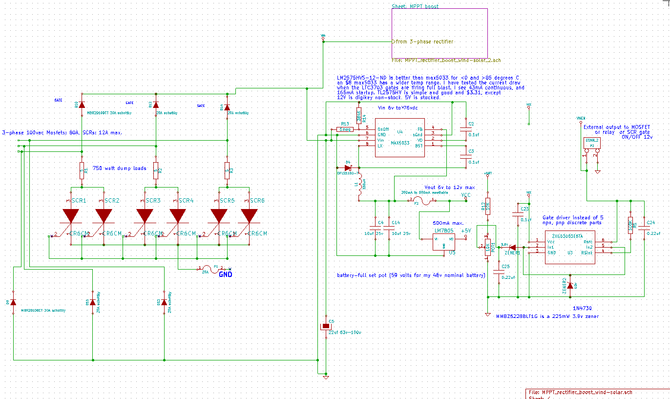
Page 1: Input from 3 Phase and powering ICs.
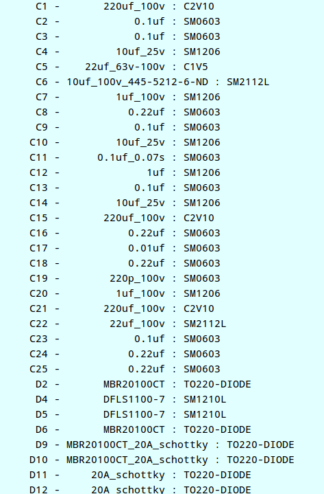
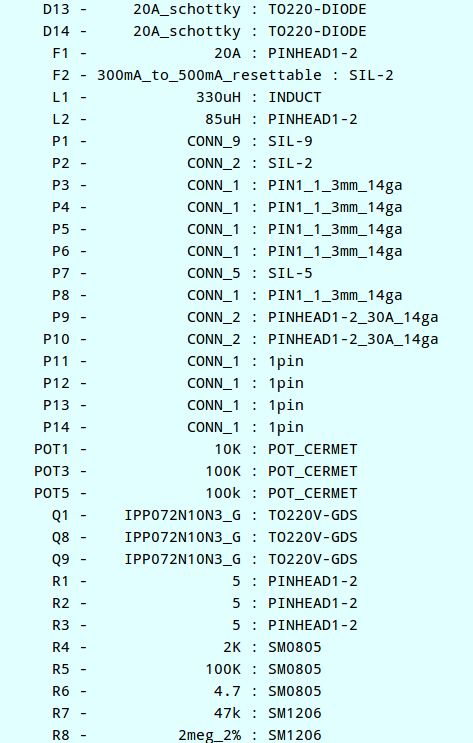
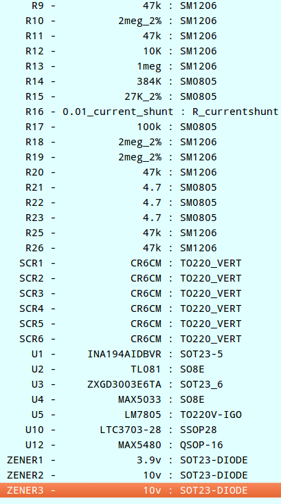
Temporary list (I'll source them from digikey.com with their part numbers later)
