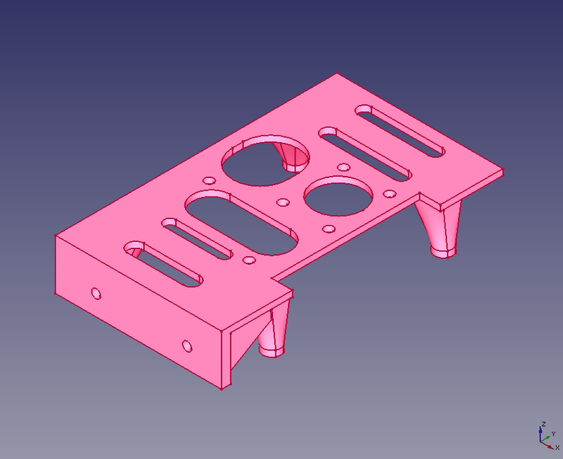
Raspberry Pi Mounting Platform and Bracket
Contents
Introduction
Still an active project, changes may be coming. This is an article started by Russ Hensel, see [[1]] for a bit of info. This project is now at github: [Parametric-Case-Enclosure].
For more pictures see: Raspberry Pi Mounting Platform and Bracket Pictures
https://github.com/russ-hensel/PiPlatform

This is a 3D printing project to solve some mounting problems with the Raspberry Pi and associated components. I am planing to use it in a variety of projects.
- I love the combination of a Raspberry Pi but how to mount them?
- I have a project that needs a small voltage regulator and USB slot. I can get them as modules, but how to mount them?
- One project is for a very humid environment, so how to I protect the electronics? ( My solution is to mount them in a jar, but how do I do that? )
What I have designed is a platform that mounts on the top ( or optionally on the bottom ) that holds the additional modules, and additionally has a bracket to mount the whole thing "standing up" so it can be mounted to the lid of a jar.
The design is intended to let you customize it to suit your particular needs:
- I am distributing it as Freecad source files so you can modify or add anything.
- Some parts are parametric so you can change some dimensions from a spreadsheet.
- The design is in parts so you can select which of the parts you want to print.
For more pictures of the printed parts see Raspberry Pi Mounting Platform and Bracket Pictures
Using the Design
Customize
Unless you are doing a project just like the design is setup for you will probably need to make at least some modifications.
Choose Your Parts
Select the parts you want to print. The platform in the title picture has the main platform, a mounting bracket and an extension. For the use on top of the Pi you will need to set the height of the platform to clear the usb jacks. Also you may want height in the platform or holes to keep the Pi cool. I have tried to give the parts somewhat useful names:
- main_platform_punched_and_ .... this is the main platform which sits on top of the Pi, pretty much all the prints of this project will include this part. It is supported by 4 feet which match up with the holes in the in the Pi. You can adjust the height above the board using the spreadsheet, and in a similar way the thickness of the platform. The next parts are optional.
- extension_platform_punched .... this extends the platform over the usb and Internet ports. Use it only if your platform is high enough to go over the ports. ( 15 mm )
- bracket_with_fillet .... this is the bracket for mounting the Pi, "standing on end".
The other parts may be used, but are not really "finished", but you might want to use them to get rid of features that you do not like.
After selecting the parts you want use ( Part workbench -> Part -> Boolean -> Union )
To help select the parts I normally make the entire model invisible ( View -> Visibility -> Hide all objects ) and then make visible ( in the model view point to the part and click the space bar ) only the parts I want to print. Then you need to also select the parts. I do this in the model view where I click on the parts I just made visible, click on the first, control click on the rest, you can see the parts selected i the 3D view.
You will get a new part: Fusion xx, you might rename it platform, but you need not keep it around long, so perhaps it does not need a rename.
Modify the Parts
You can modify the part in any way you want using FreeCad, but there are some ways that are simple and quite useful.
The Spreadsheet
If you change a value in the spreadsheet it will change some feature of the design. The two that are meant to be useful are:
- height .... this is the distance from the top of the Pi to the bottom of the platform. A setting of 15 or more lifts the platform above the usb and Internet ports. This may have several advantages, cooling, clearance, and the ability to extend the platform using the "extension_platform_punched".
- thick .... this is the thickness of the platform ( and extensions, bracket.... ). I have found that 2 mm seems to be enough, 3 mm seems super strong.
The "Punch" Sketches
If you want to mount parts to the platform you need some mounting holes. Additionally you may want to lighten up the structure by punching holes in it. Because of this most of the surfaces have sketches associated with them. All you have to do is adjust those sketches. For example add circles... and those will become holes in the associated part. Existing parts of the sketch may be deleted, or simply pushed out of the way ( off to the side of the surface they are on ) for possible reuse later.
Mesh and Export
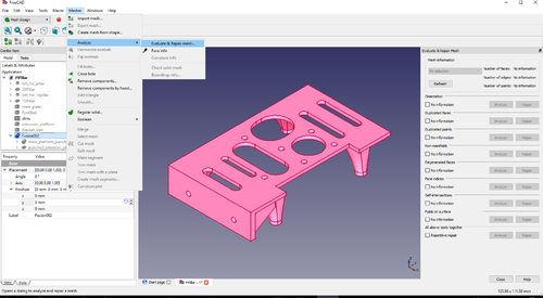
Take the fusion ( from above ), it is the whole thing that will print, you need to get it in stl format to feed your slicer. Select the fusion, and create a mesh ( Mesh Design Workbench -> Meshes -> Create Mesh from Shape -> <Standard> - <OK> ) ( I use .1mm standard mesh ) Again this creates a new part the fusion ( meshed ). It will appear right on top of the fusion so you may or may not want to tinker with the part visibilities.
My meshed parts have often had defects that create problems in printing. FreeCad has some tools for fixing them. Run them to be safe:
Meshes -> Evaluate and Repair function. Use it. Sometimes it finds things other times not. Why not be safe?
Now select the fusion ( meshed ) and use ( Any Workbench -> File -> Export ...name the file and select stl as the type ) This is the file you need to slice.
Give this a good name to make it easy to find later platform.stl perhaps.
You can find a similar workflow in another of my projects Parametric 3D Printed Electronics Case/Enclosure.
Printing
Here is what I have found useful, your results or needs may vary.
- If you software can check or repair the stl file do it.
- I almost always like a brim, a couple of mm.
- Flip this upside down, you may have guessed that.
- I have found that 50% infill is strong enough.
- So far I have used PLA. Should work in anything you can print
