MPPT Solar and Wind Power Boost Charge Controller
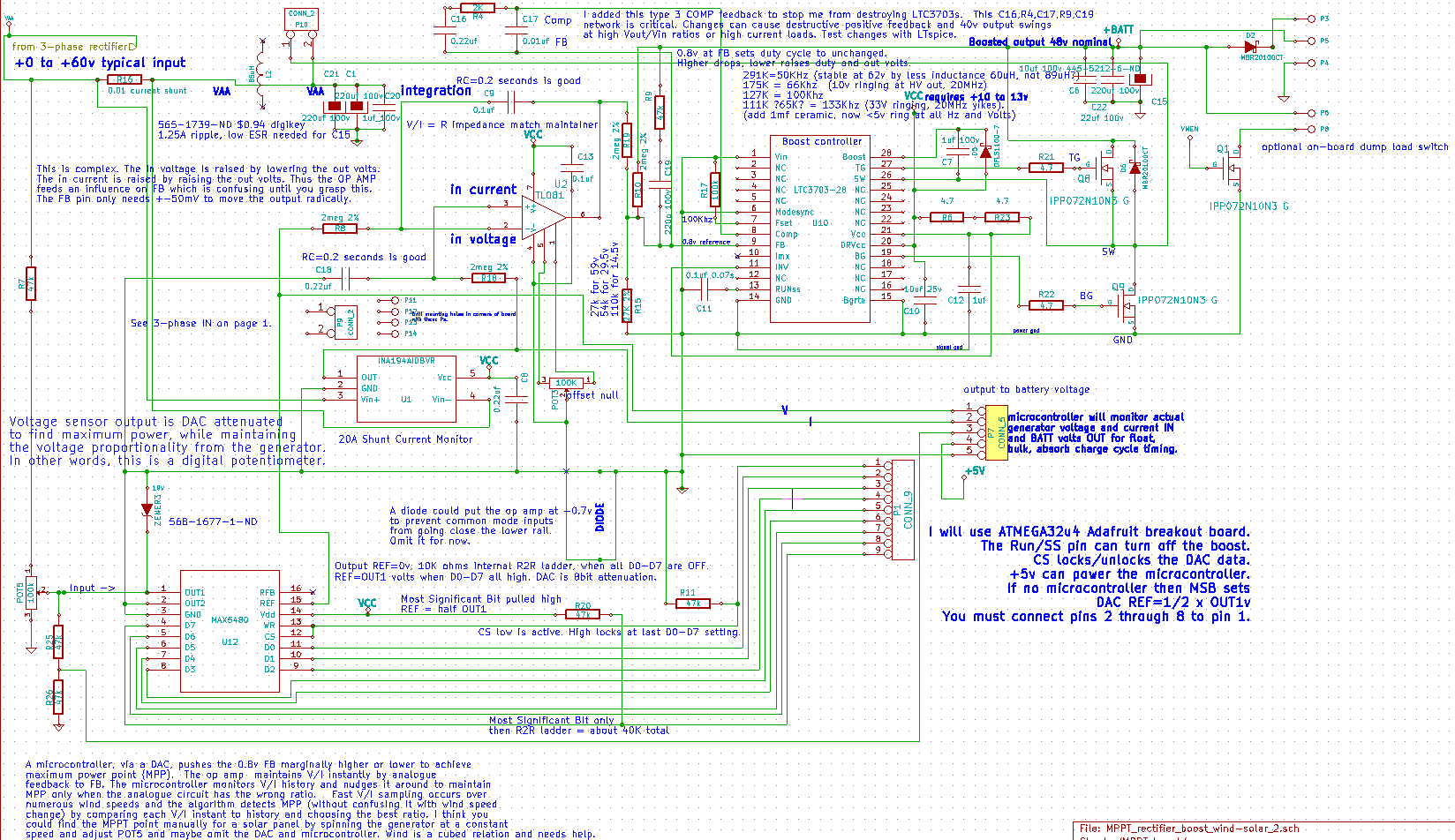
This circuit is an analogue computer, when run without a microprocessor. As rpm voltage rises, current is allowed to rise proportionally. The variable loading math is P = I(V-offset) and (V-offset)/I = R (like a fixed resistor load) and I x constant = V. The op amp pegs I equal to V. It is suitable for solar. Wind is a cubed relation, not squared extraction, like this analogue calculation will yield in wind; eg. 2I and 2V = 4P. So, it will likely need the microprocessor for optimizing wind MPPT, but without a microprocessor will be interesting. It will be better than feeding my very high voltage battery, directly because my generator rarely gets above threshold volts, which is 48v to 59v, depending on how full. In other words, it needs a boost converter. It is doing integration math, via the op amp. I added a pin header for optional microprocessor control, which I have not tested, yet.
In summary, this circuit matches a low voltage solar or wind turbine input to a higher voltage battery. An analogue circuit will measure incoming current and voltage inputs to set the maximum power point tracking (MPPT) and boost the output voltage up to charge a higher, or equal voltage, battery. Input voltage range: 9v through 60v. Output battery voltages: 9v through 60v. MPPT will work only if the battery is higher than the input source. Otherwise, the circuit will act like a direct connection, source to output. It is based on the LTC3703 boost converter IC.
I will release the board layout diagram, which is critical to success. I burned up a lot of parts with spikes, before succeeding. I have to get the new KiCAD to read my old KiCAD files.
It is 9v through 60v MPPT boost to a 48v nominal lead-acid battery. It needs more testing after I attach a wind turbine. Otherwise, it seems to work, so far. How much power can it handle? I am not sure yet. I think 500 watts minimum and maybe 1K watts with more copper over the traces.
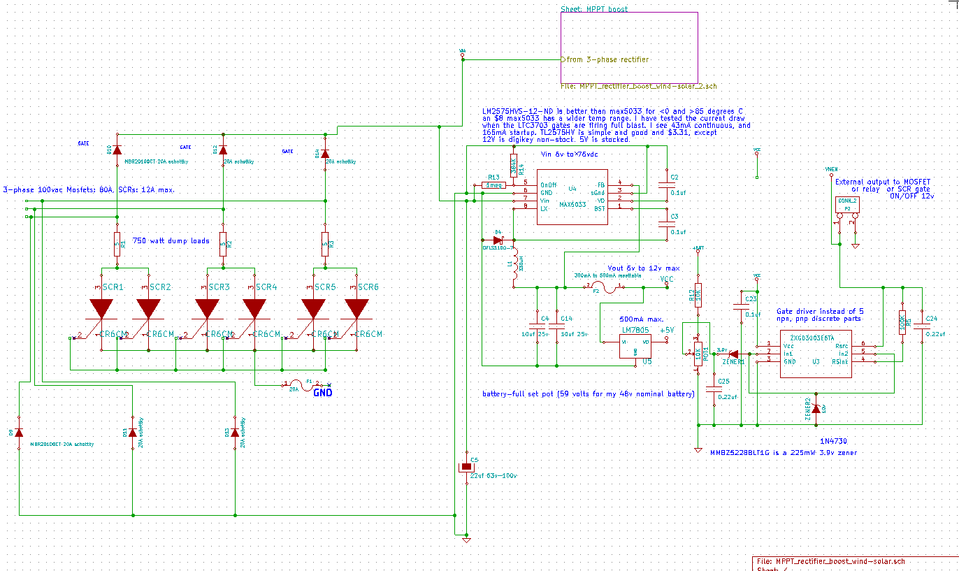
Page 1: Input from 3 Phase and powering ICs.
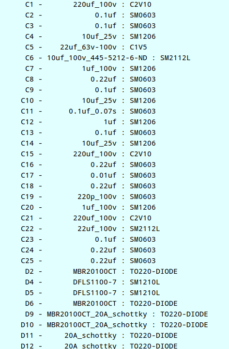
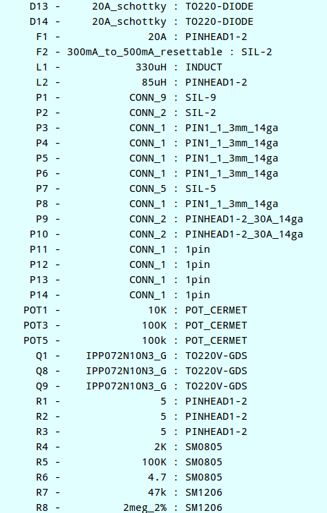
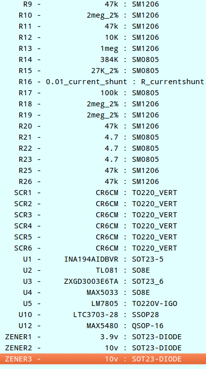
Temporary list (I'll source them from digikey.com with their part numbers later)
