Basic Circuit Building Blocks
These are circuits and parts of circuits that we see over and over again in larger projects. Understanding a complex circuit is much easier if you understand these building blocks.
Contents
- 1 Series Circuit
- 2 Parallel Circuit
- 3 Current Sense Resistor ( Shunt Resistance )
- 4 Filter Capacitor / Decoupling Capacitor / Low Pass Filter
- 5 Pull Up and Switch
- 6 Pull Down and Switch
- 7 Op amp Non Inverting Amplifier
- 8 Op amp Unity Gain Buffer
- 9 Light Emitting Diode ( with current limiting resistor )
- 10 Three Terminal Regulator
- 11 Transistor Low Side Switch
- 12 Transistor High Side Switch
- 13 Transistor Emitter Follower
- 14 Voltage Divider
- 15 Light Emitting Diode ( with current limiting resistor )
- 16 Push Pull Circuit ( with transistor emitter follower )
- 17 Darlington connected Transistors
- 18 Schmitt Trigger
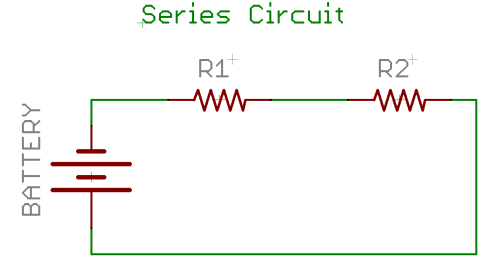
Series Circuit
In a series circuit the current first flows through one component then another and so on. The key to these circuits is that the current is the same in every element of the circuit and the total of the voltage across each of the components adds up to the voltage of the battery. A current meter is always in series with the part of the circuit whose current is being measured.
Where
- R1 resistor 1 or any other 2 terminal component, capacitor, inductor, diode....
- R2 resistor 2 or any other 2 terminal component.....
- BAT a battery or other voltage source
I you have a lot of components that use the same current put them in series. This is often how LEDs are connected to higher voltages; this also eliminates the need for a current limiting resistor on each LED. With a bit of math you can show that the two resistors act like one resistor of value R = R1 + R2 . When you need a resistor of a different value than you have you can sometimes “make it up” using a series connection of resistors you do have. To identical resistors in series are equivalent to one of double the resistance. A series circuit can have more than 2 resistors, there can be 3, 4, ... You can find out more about series circuits in the references.
More information:
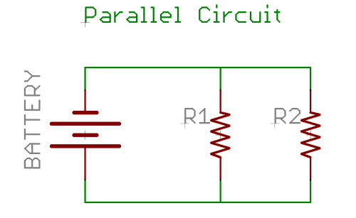
Parallel Circuit
In a parallel circuit the current divides and some flows through each component . The key to these circuits is that the voltage is the same in every element of the circuit and the total of the current through each of the components adds up to the total current from the battery. When you use a current meter it is always placed in series with the part of the circuit where you wish to measure the current.
Where
- R1 resistor 1 or any other 2 terminal component, capacitor, inductor, diode....
- R2 resistor 2 or any other 2 terminal component.....
- BAT a battery or other voltage source
Discussion:
I you have a lot of components that use the same voltage put them in parallel. This is how most lights in a house are wired. Each individual light can be turned on and off without changing the current or voltage in the other lights. With a bit of math you can show that the two resistors act like one resistor of value R = R1 + R2 /( R1 * R2 ). When you need a resistor of a different value than you have you can sometimes “make it up” using a parallel connection of resistors you do have. To identical resistors in parallel are equivalent to one of half the resistance. A parallel circuit can have more than 2 resistors, there can be 3, 4, ... You can find out more about parallel circuits in the references.
More information:
Current Sense Resistor ( Shunt Resistance )
A current Sense Resistor is a low value of resistor that is placed in series with some other circuit. We can then measure the voltage across the resistor to compute the current. If the resistor has a low value compared to other components we can ignore the effect on the circuit. We use the word shunt when the voltage is measured by a device that has a fairly low resistance itself. We then have to do a more careful calculation of how the current is shared by the two devices.
More information:
- Scienceshareware.com's How A Precision Resistor Is Used to Measure / Calculate Current and Power in an Electrical Circuit.
- High-Side Current-Sense Measurement: Circuits and Principles
- Shunt (electrical) From Wikipedia, the free encyclopedia
- Other ways to measure current: Motor_driver#current_sense
Filter Capacitor / Decoupling Capacitor / Low Pass Filter
Pull Up and Switch
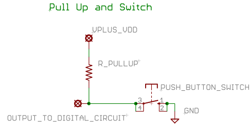
Use this circuit when you want to feed a user input to a digital circuit, for example a PIC input pin.
A pull up is a fairly high value resistor ( say 1 to 100 K ohms ) that is connected to the positive side of the power supply. This makes the other end of the resistor the same voltage as the power supply ( as long as it is connected to a high impedance. The other end of the resistor is connected to a switch that is then connected to ground. When the switch is connected current flow through the resistor dropps the entire power supply voltage and the input voltage for the circuit is now 0 (sometimes called active low, since when the switch is active the output is low). Pull up is sometimes used without the switch to keep a signal high all the time.
Circuit:
Where
- PUSH_BUTTON_SWITCH is a push button switch
- R_LED is a current limiting resistor for the LE
- R_PULLUP is the pull up resistor
- VPLUS_VDD is the power supply voltage
More information: Very Basic Circuits
Pull Down and Switch
Op amp Non Inverting Amplifier
Op amp Unity Gain Buffer
Use this circuit when you have a signal of high impedance ( can supply only a little current ) that you want to connect to another circuit that draws a significant current ( up to about 10 ma for the typical op amp. ). For example if you wish to measure the out put of a voltage divider with a 0 to 1 ma meter a unity gain buffer might be just what you need. This circuit is also know as a voltage follower.
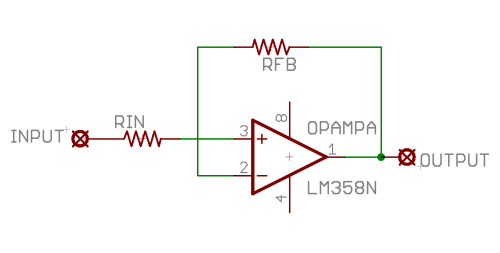
The unity gain buffer has an output voltage just the same as the input voltage. The advantage is that the input circuit does not “feel” the output. That is the input acts pretty much like a very large resistor ( many mega ohms or more ) connected to ground, and the output supply's whatever current ( up to about 10 ma ) is necessary to maintain the output voltage. Here is the circuit:
Circuit:
Where
- INPUT the input signal you wish to buffer
- RIN the input resistor, often 0 ohms.
- OPAMPA the op amp
- RFB the feed back resistor
- OUTPUT the output
The values of RIN and RFB are not very critical and are normally 0 ohms, just a straight connection. The op amp here is a quad or 4 op amp part, we are using just one section of it. Power needs to be supplied to pin 8 and 4 in the usual way for op amps.
More information:
Buffer amplifier From Wikipedia, the free encyclopedia
Light Emitting Diode ( with current limiting resistor )
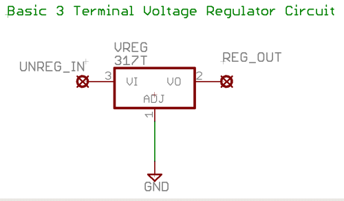
Three Terminal Regulator
Use when you need a regulated voltage and or short circuit protection.
Most circuits run better if the primary power source is a constant fixed voltage. A battery is only a poor approximation to this. Taking a battery or other voltage source ( like a wall wart plug in transformer ) and running it through a voltage regulator transforms it into a good fixed source of voltage. It also generally adds current limiting as short circuit protection. The 7805 is a very common 5 volt regulator.
Discussion:
The circuit above is very basic. Practical circuits normally include filter capacitors on both the input and the output. Most regulators protect against both over temperature and over current. Regulators come in various voltages both positive and negative. They also vary in maximum current output. There are also adjustable regulators, ways of using regular regulators as adjustable ones, and ways of boosting the current output. The spec sheets often describe how to do these things. Voltage regulators “use up” a couple of volts of the input voltage, low drop out regulators have use less, cost more. It is a good idea to check the specification for any regulator you are going to use. The LM78xx ( positive ) and LM79xx ( negative ) are quite common.
More information:
Transistor Low Side Switch
Use this circuit when you wish to turn a load on and off with both a low voltage and a low current. Note that neither side of the load is grounded.
A low side switch is one which switches a circuit on and off at the ground or low side of the circuit. The advantage of a low side switch is that when using a transistor as the switch the voltage to drive the transistor is itself a low voltage. It is often the easy way to drive leds motors and other high current devices from such low power devices as PIC output ports. Low side switche are popular and there are many integrated circuits for them as well as this circuit.
Circuit:
Where
- LED is a low power LED
- R_LED is a current limiting resistor for the LED
- Q is a bipolar transistor
- R_1 is a current limiting resistor transistor base current
- VPLUS_VDD is the power supply for the LED
The voltage at the collector of the circuit should fall to a fraction of a volt when the input is high. To acomplish this:
- Compute the value of R_LED using ohms law and the specifications for the LED.
- Compute the current through the LED.
- The transistor must supply the current, it should be equal approxtely to the input voltage divided by R1 times the beta of the transistor.
An example calculation would be nice, and will appear later.
Transistor High Side Switch
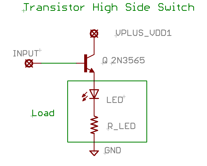
Use this circuit when you wish to turn a load on and off with a voltage at a low current. Note that low side of the load is grounded. The voltage to turn on the switch is equal to the supply voltage ( or perhaps just a bit larger )
A high side switch is one which switches a circuit on and off at the supply voltage or high side of the circuit. The advantage of a high side switch is that the load is grounded on one side. Compared to the low side switch it needs a higher voltage to drive it, but it also eliminates one resistor of that circuit. It the voltage to drive it is available it may be the circuit of choice. It is often the easy way to drive leds motors and other high current devices from such low power devices as PIC output ports.
Circuit:
Where
- LED is a low power LED
- R_LED is a current limiting resistor for the LED
- Q is a bipolar transistor
- VPLUS_VDD is the power supply for the LED
The voltage at the collector of the circuit should fall to a fraction of a volt when the input is high. To compute the values in the circuit:
- Compute the value of R_LED using ohms law and the specifications for the LED.
- The current to drive the circuit is approximately the current to drive the load divided by the beta of the transistor.
No resistor is needed into the base of the transistor because as the load draws current the voltage at the base will rise and limit the base current. The input voltage should be about equal to VPLUS_VDD, high compared to that needed for the low side switch.
Transistor Emitter Follower
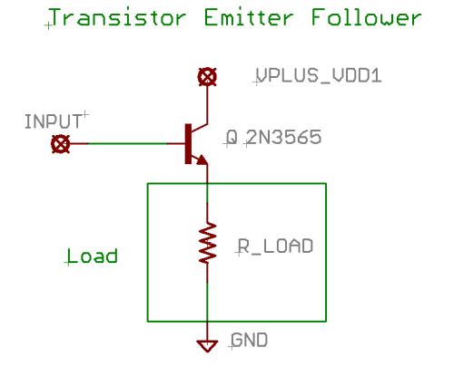
Use this circuit when you have a signal of high impedance ( can supply only a little current ) that you want to connect to another circuit that draws a significant current. The circuit has no voltage gain, but because of the current gain it has a lot of power gain. It is frequently used in the final stage of an amplifier.
This circuit is a variation of the transistor high side switch. The difference is that we typically drive this circuit in a linear way ( all of the voltages between 0 and the supply voltage ) to make it a linear amplifier.
The emitter follower is also called a common collector circuit.
Circuit:
Where
- R_LOAD represents the resistance of the load
- Q is a npn bipolar transistor
- VPLUS_VDD is the power supply for the LED
The current to drive the circuit is approximately the current to drive the load divided by the beta of the transistor. Use a Darlington connected transistor for a very high beta.
No resistor is needed into the base of the transistor because as the load draws current the voltage at the base will rise and limit the base current.
This circuit will only amplify positive voltages, using a pnp transistor you can amplify only negative voltages. Combine the two ( see push pull amplifier ) you can amplify both positive and negative voltages.
Variation of the circuit include:
- Use of coupling capacitors to amplify ac signals.
- Various other components to bias the transistor.
- Use an op amp buffer with voltage gain at the input, then the emitter follower for high current. In this way a few Milli volts with current on the order of pico amps can drive an output of several volts at an ampere or more.
More information:
Voltage Divider
Voltage Divider
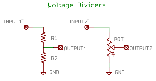
We use a voltage divider when we have a voltage that is too big and we just want a fraction ( like 1/3 or .33 ) of it. It is like an amplifier with a gain of less than 1. We use two resistors, the output is always a constant fraction of the input voltage.
Sometimes we use a potentiometer as a voltage divider. This makes the ratio of output to input adjustable. This is how we make a gain control or volume control.
Where
- R1 resistor 1
- R2 resistor 2
- POT a potentiometer
The ratio of input to output is: output/input = R2/( R1 + R2 ).
Discussion
The equation assumes that the input source is low impedance and the output is high impedance, if this is not true consider using a buffer on the input or the output ( Op Amp Unity Gain Buffer or Transistor Emitter Follower ) For audio applications a so called “log taper” pot may be used as it better matches the way in which we hear. If you want a calibrated control you may use a precision “10 turn precision” pot.
More information:
Light Emitting Diode ( with current limiting resistor )
Use this circuit to light low power LEDs
A light emitting diode can be very sensitive to small voltage changes, just a bit too much voltage and the LED will draw too much current and “burn out”. Thus it is often used with a resistor in series. If we have a 5 volt source of voltage and an LED that is specified for 2.5 volts at 10 ma, then the resistor must have ( 5 – 2.5 ) volts = 2.5 volts and 10 ma. Using ohms law 2.5/10 x 10 ee-3 = 250 ohms.
A transistor low or high side switch can be used with the resistor if your input cannot supply enough current for the LED.
Circuit: Parallel Circuit
Where
- LED the LED
- R_LED the current limiting resistor
- INPUT voltage source for lighting the LED
More information:
Push Pull Circuit ( with transistor emitter follower )
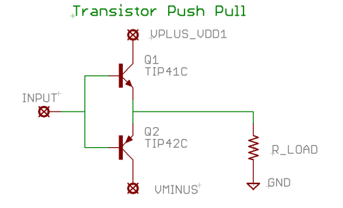
Use when you need current gain and need both positive and negative output.
A modification of the “transistor emitter follower” that can give both positive and negative outputs. Based on two transistors one npn the other pnp: one pushes the other pulls.
Where
- Q1 transistor 1 need not be a TIP41C but does need to be NPN
- Q2 resistor 2 need not be a TIP42C but does need to be PNP
- R_LOAD represents the load, here it is in the emitter, it could also be placed in the collector circuit
- VPLUS_VDD Power supply voltage, positive.
- VMINUS Power supply voltage, negative.
Discussion: Often there are other components for transistor bias or other purposes. The circuit here is really basic. The common transistors used are so called complementary pairs, similar characteristics but one npn and the other pnp. Note that we need both positive and negative power supplies. You can also put the push pull circuit inside the feedback loop of an op amp to get a high current op amplifier. Push pull amplifies can also be made with other types of transistors, tubes, or other components.
More information:
- Push-Pull Output Stage
- Class B audio amplifier
- Electronic amplifier From Wikipedia, the free encyclopedia (search on Class B and AB )
Darlington connected Transistors
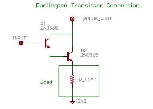
Use a Darlington transistor connection when you want really high current gain. Gain of 1000 is easily in reach. That is 1 ma to 1 amp This is a useful connection of 2 transistors that together form a transistor of much larger gain. You can also buy Darlington transistors all packaged in a single case with just 3 connections exposed to the outside.
Where
- Q1 transistor 1 need not be a 2N3565 but does need to be NPN
- Q2 resistor 2 need not be a 2N3565 but does need to be NPN
- R_LOAD represents the load, here it is in the emitter, it could also be placed in the collector circuit
- VPLUS_VDD Power supply voltage, positive.
Discussion:
Often Q1 is a high gain small signal transistor and Q2 a lower gain power transistor. You can use PNP transistors by using a negative power supply. Use a ULN2803 ( or similar chips ) to get 8 darlingtons in one package, useful as low side switches and in conjunction with microcontrollers.
More information:
- http://en.wikipedia.org/wiki/Darlington_transistor Darlington transistor From Wikipedia, the free encyclopedia]
- Transistor Circuits ( search on Darlington )
- Lessons In Electric Circuits -- Volume III Chapter 4 BIPOLAR JUNCTION TRANSISTORS Darlington pair ( search on Darlington )
