Difference between revisions of "Raspberry Pi Mounting Platform and Bracket Pictures"
Russ hensel (talk | contribs) |
Russ hensel (talk | contribs) |
||
| (16 intermediate revisions by the same user not shown) | |||
| Line 1: | Line 1: | ||
| − | These are actual prints of the mount described in [[ | + | These are actual prints of the mount described in [[Raspberry Pi Mounting Platform and Bracket]] |
| + | This page has several pictures of the printed parts discussed in [[Raspberry Pi Mounting Platform and Bracket]] | ||
| + | There are some different variations of the part, and some are shown with additional parts mounted and some without. Pictures are taken from different angles. | ||
| + | |||
| + | This is an article started by Russ Hensel, see "http://www.opencircuits.com/index.php?title=Russ_hensel#About My Articles" '''About My Articles''' for a bit of info. The page is only partly finished | ||
| + | |||
| + | |||
| + | = Small Platform With Voltage Regulator = | ||
| + | |||
| + | Here a voltage regulator and usb power output port are mounted on top of the Pi. The blue and white wires are for a power supply to run the regulator and thus the Pi. In this case I needed a basic supply to run two stepper motors and wanted to use the same power source for the Pi. The parts are mounted with melted rivets a method I am just messing about with. | ||
[[Image:Pp3.JPG|500px]] | [[Image:Pp3.JPG|500px]] | ||
| + | This is from the side with the hdmi port | ||
| + | |||
| + | [[Image:Pp small1.JPG|500px]] | ||
| + | |||
| + | |||
| + | This is from the side of the Pi with its IO headers | ||
| + | |||
| + | |||
| + | [[Image:Pp small4.JPG|500px]] | ||
| + | |||
| + | = A Variation = | ||
| + | |||
| + | In this case there is no Pi, no wires and the parts are mounted with bolts ( too long waiting for the right ones to arrive ) not melted rivets. | ||
| + | |||
| + | [[Image:Pp7.JPG|500px]] | ||
| + | |||
| + | = Arduino Over a Pi = | ||
| + | |||
| + | No wires yet, a bit of hot glue holds the arduino in place. The arduino mount is bolted to the Pi bracket as both would not print well at once. Note that all pins at this end are available for connections. | ||
| + | [[Image:pp8.JPG|500px]] | ||
| + | |||
| + | |||
| + | This view from the USB accessory port end. | ||
| + | |||
| + | [[Image:pp9.JPG|500px]] | ||
| + | |||
| + | |||
| + | Better view of most of the pins. | ||
| + | [[Image:pp10.JPG|500px]] | ||
| + | |||
| + | |||
| + | This is how the bracket is intended to be connected to a surface. | ||
| + | [[Image:pp12.JPG|500px]] | ||
| + | = Large Platform No Componets = | ||
| + | This is a large platform with a mounting bracket. It is bad because the normal top mount | ||
| + | will cover the Raspberry Pi pins. Still can be used, Access the pins another way, cut into it | ||
| + | or bottom mount it. For bottom mounts the legs need not bee so long. | ||
| − | |||
| − | [[Image: | + | [[Image:Pp1.JPG|500px]] |
| + | |||
| − | |||
| − | [[ | + | [[Category:Arduino/RaspberryPi]] [[Category:FreeCad]] [[Category:CAD/3DPrint]] |
Latest revision as of 07:27, 26 January 2018
These are actual prints of the mount described in Raspberry Pi Mounting Platform and Bracket
This page has several pictures of the printed parts discussed in Raspberry Pi Mounting Platform and Bracket
There are some different variations of the part, and some are shown with additional parts mounted and some without. Pictures are taken from different angles.
This is an article started by Russ Hensel, see "http://www.opencircuits.com/index.php?title=Russ_hensel#About My Articles" About My Articles for a bit of info. The page is only partly finished
Contents
Small Platform With Voltage Regulator[edit]
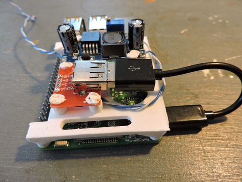
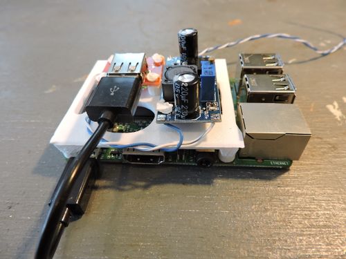
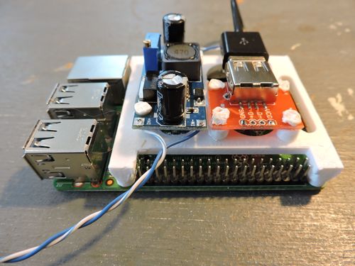
Here a voltage regulator and usb power output port are mounted on top of the Pi. The blue and white wires are for a power supply to run the regulator and thus the Pi. In this case I needed a basic supply to run two stepper motors and wanted to use the same power source for the Pi. The parts are mounted with melted rivets a method I am just messing about with.
This is from the side with the hdmi port
This is from the side of the Pi with its IO headers
A Variation[edit]
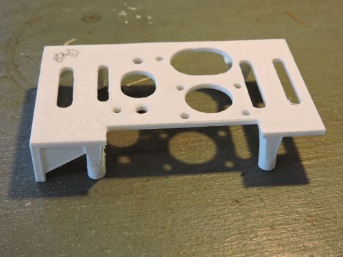
In this case there is no Pi, no wires and the parts are mounted with bolts ( too long waiting for the right ones to arrive ) not melted rivets.
Arduino Over a Pi[edit]
No wires yet, a bit of hot glue holds the arduino in place. The arduino mount is bolted to the Pi bracket as both would not print well at once. Note that all pins at this end are available for connections.

This view from the USB accessory port end.
Better view of most of the pins.

This is how the bracket is intended to be connected to a surface.

Large Platform No Componets[edit]
This is a large platform with a mounting bracket. It is bad because the normal top mount will cover the Raspberry Pi pins. Still can be used, Access the pins another way, cut into it or bottom mount it. For bottom mounts the legs need not bee so long.


