Difference between revisions of "Solderless protoboard"
Russ hensel (talk | contribs) |
Russ hensel (talk | contribs) (add links) |
||
| Line 34: | Line 34: | ||
*[http://www.instructables.com/id/Breadboard-Layout-Sheets-plug-and-play-electronic/ Solderless Breadboard Layout Sheets (plug and play electronics)] | *[http://www.instructables.com/id/Breadboard-Layout-Sheets-plug-and-play-electronic/ Solderless Breadboard Layout Sheets (plug and play electronics)] | ||
| + | |||
| + | *[http://en.wikipedia.org/wiki/Breadboard Wikipedia:Breadboard] | ||
| + | |||
| + | *[http://www.best-microcontroller-projects.com/prototyping.html a simple example with a small microcontroller] | ||
*Fairly closely related to bread/proto boards are development boaards. Typically they have some basic circuitry ( a power supply and a microprocessor for example ) and a area for prototyping. See [[Microcontroller#Development_Boards]]. | *Fairly closely related to bread/proto boards are development boaards. Typically they have some basic circuitry ( a power supply and a microprocessor for example ) and a area for prototyping. See [[Microcontroller#Development_Boards]]. | ||
Revision as of 09:04, 14 February 2011
The title of this page may need to be changed. There is a lot of loose usage of protoboard, proto-board, breadboard.... In any case they all seem to come back in some way to more casual, one off methods of circuit construction. Breadboard, I have heard, originated in the early days of electronics when the wooden kitchen breadboard was re-purposed to be the foundation of a circuit. Cooks beware. Perhaps their highest form was in the Atwater Kent Breadboard Receivers The online Museum of Atwater Kent Breadboard Receivers and Atwater Kent Breadboard Receivers).
There are many links to the topic:
- Fairly closely related to bread/proto boards are development boaards. Typically they have some basic circuitry ( a power supply and a microprocessor for example ) and a area for prototyping. See Microcontroller#Development_Boards.
More Tips
- Lots of people grab a component and shove it in. Can make a mess, unless you are in a real hurry cut the leads to a proper length.
- Using needle nose pliers to put the components in can help prevent curmpling of the leads.
- Many parts have leads that are to small to stand up to the pressure. Solder them on to headers to give them nice strong, easily inserted leads.
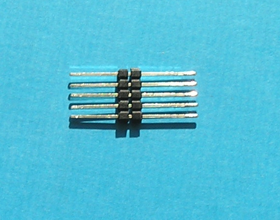
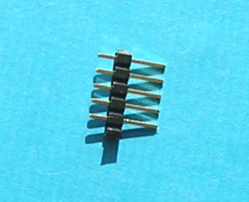
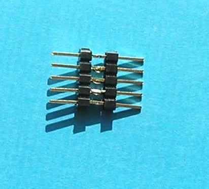
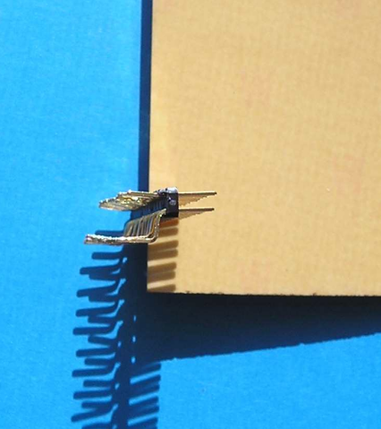
- In one salvage job I found some "double ended" headers, long pins on both ends. These can be very handy because once plugged in they can be used to let you plug in female connectors ( like those on hard drive cables ( but just one of the two sides ) to the board. See pictures below. Hard part to find. But wait, you can solder two regular headers back to back.
The found "long" header:
Normal header:
- Expanding on the "double ended" header above.
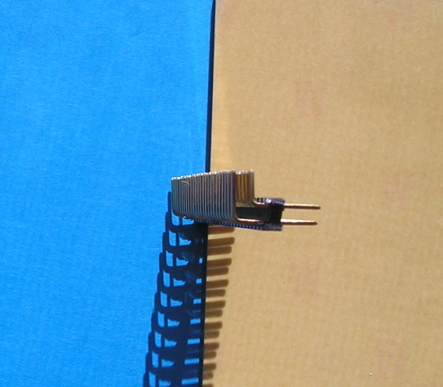
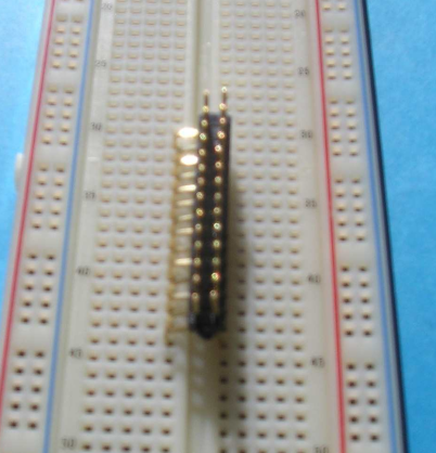
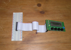
Right angle headers are long enough to bend the pins so they are long on both sides. Take a dual row one and bend the pins to fit across the gap at the center of the proto board. Then you can plug in a dual plug like those on hard drive cables. Pictures may make the idea clearer:
Put it in the center
